

An antenna datasheet answers four questions: Does it cover your bands and match 50 Ω (frequency range, VSWR, impedance)? Where does the energy go (gain, beamwidth, front-to-back ratio, downtilt)? Can it share a site (polarization, isolation, PIM)? Will it survive the installation (power, connectors, wind, temperature, lightning protection)? Values marked ≤ or ≥ are limits across the whole band, and multiband models list each band separately.
Last updated: November 2026
What an Antenna Datasheet Tells You
An antenna datasheet lists the electrical and mechanical specifications of one antenna model, and a full PDF datasheet adds the measured VSWR sweep and radiation patterns behind those figures. Read it as a set of limits and per-band values, then check the curves.
Take the datasheet for the BBT-0627PA1417D065 sector panel antenna, a dual-band ±45° panel for 4G LTE base station coverage. It follows the layout used across BBT products. Page 1 holds two tables: Electrical (bands, polarization, gain, beamwidth, VSWR, intermodulation, downtilt, front-to-back ratio, impedance, power and lightning protection) and Mechanical (connectors, dimensions, radome, temperature and pole size). The Mechanical table finishes at the top of page 2 with the wind rating, and the rest of page 2 shows the VSWR sweep plus an H-plane and E-plane radiation pattern for each band. You can download the full datasheet (PDF) and follow along.
Three reading rules apply to every line:
- ≤ is a ceiling and ≥ is a floor. VSWR ≤2.0 is the upper limit for every frequency in the operating bands, and Front to Back Ratio ≥25dB is the lower limit. Neither is a single reading at one frequency.
- Multiband values follow band order. When a line carries one value per band column, each value belongs to the band listed at the top of its column: 14dBi applies to 698–960 MHz and 17dBi to 1710–2700 MHz. A single value spread across both columns applies to both bands.
- H-Plane is horizontal and E-Plane is vertical. On BBT datasheets, the 3dB Beam-Width H-Plane figure describes how wide the coverage is, and the E-Plane figure describes the vertical beam.
Here is the BBT-0627PA1417D065 datasheet line by line. The middle column shows each value exactly as printed in the PDF.
| Datasheet line | Value on this datasheet | What it tells you |
|---|---|---|
| Electrical | ||
| Part Number | BBT-0627PA1417D065 | The model code. Use it to match the PDF, the product page and any quotation, so everyone is discussing the same antenna. |
| Frequency Range | 698-960MHz / 1710-2700MHz | Two operating bands. Every other value on the sheet applies inside these ranges only. |
| Polarization Type | ±45° | Slant dual polarization: two orthogonal ports in one radome, used for 2×2 MIMO or diversity. |
| Gain | 14dBi / 17dBi | Peak gain per band, in dBi: 14 dBi at 698–960 MHz and 17 dBi at 1710–2700 MHz. |
| 3dB Beam-Width, H-Plane | 65° / 65° | Horizontal coverage width in each band. 65° is the usual width for a three-sector site. |
| 3dB Beam-Width, E-Plane | 16° / 8° | Vertical beam. It halves in the high band, so the upper-band beam is thinner and needs more careful tilt. |
| VSWR | ≤2.0 | Ceiling for the impedance match across both bands. At 2.0, about 11% of the power is reflected. |
| Intermodulation IM3 (2×43 dBm carrier) | ≤-150dBc | PIM rating with its test condition: two 20 W carriers, with the third-order product at least 150 dB below the carrier. |
| Electrical Downtilt (°) | 0° | No built-in tilt. Any downtilt has to be mechanical, set by angling the antenna at installation. |
| Front to Back Ratio | ≥25dB | Rear radiation at least 25 dB below the front, about 1/316 of the forward signal. |
| Input Impedance | 50Ω | Matches standard 50 Ω radios, coaxial cables and connectors. |
| Max Input Power | 100W | Highest RF input the antenna is rated for. Transmitter power at the antenna port must stay below it. |
| Lightning Protection | DC Grounded | The radiating structure is grounded at DC, giving surge current a path to the mast earth. |
| Mechanical | ||
| Connector Type | 2×7/16DIN Female | Two ports, one per polarization, with 7/16 DIN female connectors. Jumpers need 7/16 DIN male ends. |
| Dimensions H*W*D (mm) | 1380*280*130(mm) | Height, width and depth. Check them against mast space, wind area and shipping volume. |
| Radome Material | PVC | Material of the housing that covers the radiating elements. |
| Radome color | gray | Housing color, relevant where a site has to blend into its surroundings. |
| Operating Temperature Range | -40ºC/+60ºC | Ambient temperature range for operation. |
| Support Pole Diameter | φ30-φ60(mm) | The bracket clamps poles from 30 to 60 mm in diameter. |
| Rated Wind Velocity | 60m/s | Wind speed the antenna and bracket are rated to withstand. Printed at the top of page 2. |
Page 2 backs two of these lines with measured evidence. The VSWR plot is a network analyzer sweep from 698 to 2700 MHz, with markers at both edges of each band, and the ≤2.0 in the table is the ceiling for that curve inside both operating bands. The radiation patterns give one H-plane and one E-plane cut per band, and they are where the 65°, 16° and 8° beamwidths come from. When a datasheet prints these figures without any curves, you have nothing to check them against.
Typical Datasheet Values by Antenna Type
Whether a value is good depends on the antenna type: 3 dBi is normal for a ceiling antenna and 30 dBi for a dish, so judge each datasheet against its own category. The ranges below come from BBT datasheets across 11 antenna types.
| Antenna type | Gain | VSWR (worst band) | Horizontal beamwidth | Front-to-back ratio | PIM or port isolation | Max input power |
|---|---|---|---|---|---|---|
| Outdoor omni (fiberglass) | 2–15 dBi | ≤1.5 on most models | 360° (vertical 5°–80°, narrower as gain rises) | Not listed | Not listed | 20–120 W |
| Ceiling (indoor DAS) | 2–6 dBi | Listed per band, ≤1.5–2.0 | 360° | Not listed | PIM ≤-150 dBc on most models; isolation ≥15–23 dB on MIMO models | 50 W on most models |
| Wall-mount (indoor DAS) | 5–9 dBi | ≤1.5–2.0 | 90° | ≥15–20 dB | PIM ≤-150 dBc on half the models; isolation ≥20–30 dB on MIMO models | 50 W |
| Sector / base station panel | 6–20 dBi | ≤1.4–2.0 | 65°, 90° or 120° | ≥15–30 dB | PIM ≤-150 dBc on some models | 50–100 W on most models |
| Narrow-beam flat panel (point-to-point, CPE) | 14–26 dBi | ≤1.5–2.0 | 6°–38° | ≥15–30 dB | Not listed | 50–100 W |
| Solid parabolic dish | 17–34 dBi | ≤1.5–2.0 | 3°–20° | ≥25–40 dB | Not listed | 100 W |
| Grid / mesh parabolic | 10–29 dBi | ≤1.5 on most models | 6°–30° on most models | ≥15–30 dB | Isolation ≥15–25 dB on dual-polarized models | 100–200 W |
| Horn | 15.5–20.5 dBi | ≤2.0 | 15°–40° | ≥25 dB | Isolation ≥25 dB | 100 W |
| Yagi | 4–17 dBi | ≤1.5 on most models | 25°–75° on most models | ≥10–20 dB | Not listed | 50–100 W |
| Log-periodic | 9–11 dBi | ≤1.5–2.0 | 65° on most models | Not listed | PIM ≤-150 dBc on most models | 100 W |
| UHF RFID panel | 2–12 dBi | ≤1.3 or ≤1.5 | 20°–90° | ≥10–25 dB | Not listed | 20 W on most models |
Ranges are taken from BBT ANTENNAS product datasheets, November 2026. PIM figures are IM3 with 2×43 dBm carriers. “Not listed” means the datasheets for that type carry no such line.
“Not listed” is normal for some types. An omni antenna radiates all the way around, so it has no back to measure, and its datasheet lists no front-to-back ratio. Most UHF RFID panels list VSWR ≤1.3 or ≤1.5. Solid dishes post the highest front-to-back ratios in the range, up to ≥40 dB. For how gain and beamwidth trade off across these types, see our comparison of high-gain antenna types.
Example BBT Datasheets by Application
Each of these four datasheets puts one reading point from this guide into practice: PIM with its test power on a base station panel, isolation per band on a 4T4R ceiling antenna, gain and beamwidth per band on a wideband grid, and a ≤1.3 VSWR on a UHF RFID antenna.

Dual-Polarized Sector Panel Antenna
BBT-0609PA14D065
Lines to check: IM3 and front-to-back ratio
698–960 MHz · 14 dBi · ±45°
H 65° / E 16° · VSWR ≤2
IM3 ≤-150 dBc (2 × 43 dBm) · F/B ≥25 dB
0° electrical tilt · 100 W · 2 × 7/16 DIN Female
1300 × 280 × 130 mm · 60 m/s wind rating
View Detail

4T4R MIMO Ceiling Antenna
BBT-0660CL0306H4
Line to check: port isolation in each band
617–960 / 1710–2700 / 3300–4200 / 4900–6000 MHz
3 / 4.5 / 5.5 / 6 dBi · H 360° · E 60° / 50° / 35° / 30°
VSWR ≤1.8 · isolation ≥15 / 20 / 23 / 23 dB
IM3 ≤-150 dBc · 50 W
4 × 4.3-10 Female · Φ360 × 18 mm
View Detail
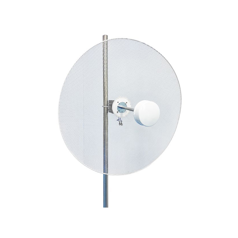
600–6000 MHz Wideband Grid Antenna
BBT-0660PW1321VH09
Lines to check: gain and beamwidth in each band
600–960 / 1710–2700 / 3300–4200 / 4200–6000 MHz
13 / 21 / 20 / 19 dBi · H 30° / 13° / 10° / 8° (±5°)
VSWR ≤2.0 · F/B and isolation ≥15 / 22 / 25 / 25 dB
H/V dual-pol · 100 W · 2 × N-Female
Φ900 mm · 60 m/s wind rating
View Detail

5 dBi Circular-Polarized UHF RFID Antenna
BBT-RFID09C05-145
Line to check: VSWR ≤1.3
902–928 MHz · 5 dBi · RHCP
H 80° / E 70° · VSWR ≤1.3 · F/B ≥17 dB
20 W · SMA Male on LMR200 cable
145 × 145 mm · -25 °C to +65 °C
View Detail
Frequency Range, VSWR and Impedance
An antenna only meets its datasheet inside the frequency ranges it lists, and VSWR shows how well it accepts power across those ranges. Check the band edges first, then the VSWR ceiling, then the impedance.
The frequency range must cover every channel your radios use, edge to edge. A 698–960 MHz antenna serves the 700, 800 and 900 MHz cellular bands but not 617–698 MHz. Multiband antennas list separate ranges with gaps between them: the BBT-0627PA1417D065 covers 698–960 and 1710–2700 MHz and specifies nothing between 960 and 1710 MHz. Antennas with more bands work the same way: the BBT-0660CL0306H4 4T4R ceiling antenna lists four separate bands, 617–960, 1710–2700, 3300–4200 and 4900–6000 MHz, with its own gain, beamwidth and isolation values for each band.
Input impedance is 50 Ω on almost all infrastructure antennas, matching standard radios, coaxial cable and connectors. Across BBT datasheets, only one model is specified at 75 Ω. The VSWR on a datasheet is measured against the impedance it states.
What Is a Good VSWR for an Antenna?
VSWR ≤1.5 is a tight match, and ≤2.0 is common on wideband and multiband antennas. At those limits, the difference is 4.0% versus 11.1% of the power reflected, or 0.18 dB versus 0.51 dB of mismatch loss.
BBT datasheets show the spread by type: UHF RFID panels list ≤1.3 or ≤1.5, most omni and grid antennas ≤1.5, and wideband multiband ceiling and panel antennas ≤1.8 to ≤2.0. A wider band is harder to match evenly, which is why multiband designs sit at the higher end. Whatever the figure, it should be the ceiling across each full band. A value such as “VSWR 1.2 at 915 MHz” describes one frequency and says nothing about the band edges.
VSWR vs Return Loss
VSWR and return loss measure the same reflection on two scales. VSWR falls toward 1.0 as the match improves, while return loss in dB rises, so VSWR 1.5 equals 14.0 dB of return loss, and VSWR 2.0, often written 2:1, equals 9.5 dB.
That also answers what return loss is acceptable: 14 dB or more puts an antenna in the ≤1.5 class, and 9.5 dB or more in the ≤2.0 class. Some datasheets print return loss as S11 with a minus sign, such as -14 dB, which is the same figure.
| VSWR | Return loss | Reflected power | Mismatch loss |
|---|---|---|---|
| 1.2 | 20.8 dB | 0.8% | 0.04 dB |
| 1.3 | 17.7 dB | 1.7% | 0.07 dB |
| 1.5 | 14.0 dB | 4.0% | 0.18 dB |
| 1.7 | 11.7 dB | 6.7% | 0.30 dB |
| 1.8 | 10.9 dB | 8.2% | 0.37 dB |
| 2.0 | 9.5 dB | 11.1% | 0.51 dB |
| 2.5 | 7.4 dB | 18.4% | 0.88 dB |
Return loss, reflected power and mismatch loss are calculated from VSWR and rounded.
Why VSWR Alone Does Not Prove Performance
VSWR shows how much power gets into the antenna and says nothing about where that power goes. A 50 Ω dummy load has an almost perfect VSWR and radiates nothing, so a good VSWR only means something when gain and radiation patterns measured on the same antenna back it up. We check VSWR on network analyzers and measure gain and patterns in our in-house microwave chamber, and our article on anechoic chamber testing shows how those measurements are made.
Gain, Beamwidth, Front-to-Back Ratio and Downtilt
Gain tells you how strongly an antenna concentrates energy, while beamwidth, front-to-back ratio and downtilt tell you where that energy lands. Read all four for each band, because they change with frequency.
Gain is quoted per band, so “14dBi / 17dBi” on a dual-band panel means 14 dBi in the low band and 17 dBi in the high band. Check the unit as well. dBi is referenced to an isotropic radiator and dBd to a half-wave dipole, and dBi = dBd + 2.15, so 12 dBd equals 14.15 dBi. Our guide to dB, dBi and dBm covers the units, and antenna gain vs directivity explains how gain relates to beam shape.
Horizontal and Vertical Beamwidth
The 3 dB beamwidth is the angle between the two directions where radiated power falls to half of the peak. The H-Plane figure sets how wide the coverage is. The E-Plane figure sets how the beam spreads vertically, which affects how far it reaches and whether users close to the mast sit inside the beam or below it.
On the BBT-0627PA1417D065, the horizontal beam stays at 65° in both bands while the vertical beam narrows from 16° to 8° in the upper band. The 17 dBi high band therefore packs its energy into a thinner vertical slice and needs more careful aiming. A 65° horizontal beam is the usual building block of a three-sector site, and our sector antenna guide compares 65°, 90° and 120° sectors.
Electrical Downtilt shows whether the vertical beam is tilted inside the antenna. A value of 0° means no built-in tilt, so any downtilt has to be mechanical, set by angling the antenna during installation. Models with electrical tilt print the angle, as one of our 5 GHz dual-polarized panels does with 4°.
How to Read the Radiation Pattern Plots
Radiation patterns are polar plots. The antenna sits at the center, angles run around the edge, and the rings mark signal level in dB below the peak. The angle between the two points where the main lobe crosses the -3 dB ring is the beamwidth in the table. The lobe pointing the opposite way, at 180°, is the back lobe, and the drop from the main lobe to the back lobe is the front-to-back ratio. Smaller lobes beside the main beam are side lobes. Page 2 of a BBT PDF datasheet gives one H-plane plot and one E-plane plot per band, so a dual-band panel has four.
Front-to-Back Ratio
Front-to-back ratio compares the forward peak with the signal radiated backwards. A ratio of 20 dB means the rear signal is 1/100 of the front, 25 dB means 1/316 and 30 dB means 1/1000. Most BBT sector panels list ≥25 dB, solid dishes reach ≥38 to ≥40 dB, and omni antennas do not list the figure because they have no back. A high ratio keeps a sector from spilling into the area behind it and helps antennas mounted back to back on one tower stay apart.
Polarization, Port Isolation and PIM
Polarization, isolation and PIM decide whether an antenna can share a site, a radio or a cable run with other equipment without degrading it. They matter most on MIMO, multi-operator and multi-carrier systems.
Polarization
Polarization has to match the other end of the link or the radio port. Vertical (V) or horizontal (H) single polarization is common on omni, Yagi and point-to-point antennas. ±45° slant dual polarization puts two ports in one radome for MIMO on base station and DAS panels, and H/V dual polarization does the same on horns and some grid antennas. RHCP circular polarization lets UHF RFID readers pick up tags at any orientation. Our guide to linear vs circular polarization compares the options.
Port-to-Port Isolation
Port-to-port isolation is how much of the signal fed into one port leaks out of another port on the same antenna, so higher is better: 20 dB lets 1/100 of the power through and 25 dB about 1/316. Where BBT dual-port models list isolation, the figure is mostly ≥20 to ≥25 dB. Isolation is usually lower in the low band, as the BBT-0660CL0306H4 4T4R ceiling antenna shows with ≥15 / 20 / 23 / 23 dB across 617–960, 1710–2700, 3300–4200 and 4900–6000 MHz. On dual-polarized and MIMO antennas, look for a figure in every band. Our guide to dual-polarized antenna selection shows where isolation fits into the choice.
Passive Intermodulation (PIM)
A PIM line such as “Intermodulation IM3 (2×43 dBm carrier) ≤-150dBc” means two test carriers of 43 dBm (20 W) each are applied, and the third-order product they create stays at least 150 dB below the carrier, which is -107 dBm or lower. PIM figures compare only at the same test power, so -150 dBc at 2×43 dBm and a figure measured at a lower power are different claims. Connectors play a part too: 4.3-10 and 7/16 DIN interfaces are common on PIM-rated base station and DAS antennas. Our guide on how to compare PIM ratings goes into test conditions and project requirements.
Power Handling, Connectors and Mechanical Specs
The power, connector and mechanical lines tell you whether the antenna will connect to your cabling and survive your site. Check them before approving a model, since a perfect band match does not help if the bracket does not fit the pole.
- Max Input Power: the highest RF input the antenna is rated to handle. BBT RFID and indoor antennas are mostly rated 20–50 W, and outdoor base station, dish and grid antennas reach 100–200 W. Keep the transmitter power at the antenna port below the rating, with margin for multiple carriers.
- Connector Type: the number in front is the port count, so “2×7/16DIN Female” means two 7/16 DIN female ports. Common types are N, 7/16 DIN, 4.3-10, SMA and TNC. Check the gender as well as the type, so your jumpers fit without adapters.
- Lightning Protection: “DC Grounded” means the radiating structure is connected to ground at DC, giving static charge and lightning surges a path to the mast earth. Your site still needs its own grounding and surge protection.
- Dimensions, weight and Support Pole Diameter: check size and weight against mast space, wind load and shipping. Most BBT outdoor brackets fit φ30–60 mm poles, and some models take φ35–50 mm.
- Rated Wind Velocity: the wind speed the antenna and bracket are rated for. BBT outdoor models list 60 m/s.
- Operating Temperature Range: most BBT models are rated -40 °C to +60 °C.
- Radome Material: PVC and ABS are common on panels and indoor antennas, and fiberglass on outdoor omni antennas.
How to Compare Two Antenna Datasheets
Two datasheets compare fairly only when the bands, units and test conditions match. Work through these checks before you decide one antenna beats another:
- Bands: are the frequency ranges identical, edge to edge? 617–960 MHz and 698–960 MHz are different antennas.
- Gain: is each gain figure for the same band and in the same unit? Add 2.15 to a dBd value to compare it with dBi.
- VSWR: is it a ceiling across the whole band or a reading at one frequency?
- Beamwidth: are both the horizontal and the vertical beamwidth given for each band?
- PIM: were both figures measured at the same test power, such as 2×43 dBm?
- Isolation: do dual-polarized and MIMO models list isolation for every band?
- Mechanical fit: do the wind rating, pole diameter, connector type and connector gender suit your site?
- Evidence: does the datasheet include a VSWR sweep and radiation patterns for each band? If a value is missing, ask the supplier for it before you compare.
If you are still choosing the antenna type for a macro site, our guide to choosing a base station antenna covers that step.
Our engineers will match a BBT antenna to the specs on your datasheet and send you a quote as soon as possible.
Get a Spec-Matched QuoteWhy Project Buyers Trust BBT ANTENNAS Datasheets
BBT ANTENNAS publishes one datasheet format across base station, DAS, backhaul and RFID antennas, lists every band separately and backs key figures with measured curves. That makes our models quick to compare and easy to verify.
- One layout, band by band: Electrical and Mechanical tables with fixed line names, and separate values for each band on multiband models.
- Curves in the PDF: H-plane and E-plane patterns for each band, with VSWR sweeps on many models.
- Test conditions on the page: our PIM-rated DAS and base station models list IM3 ≤-150 dBc together with the 2×43 dBm test condition, and our MIMO ceiling and wall-mount DAS antennas, horns and dual-polarized grid and mesh parabolic antennas list isolation band by band.
- In-house measurement: network analyzers, third-order intermodulation testers and a microwave anechoic chamber (see anechoic chamber testing), plus constant temperature and humidity, rain, salt-spray and drop test equipment.
- Certified, established production: ISO 9001:2015 and ISO 14001:2015, an antenna history that began in 1991, more than 200 staff, a 30,000 m² R&D and production workshop and four-stage quality control.
We also offer OEM/ODM development for projects that need custom bands, connectors or private-label branding.
Antenna Datasheet FAQ
What is a good VSWR for an antenna?
VSWR ≤1.5 is a tight match, and ≤2.0 is common on wideband and multiband antennas. At those limits, 4.0% of the power is reflected at 1.5 with 0.18 dB of mismatch loss, and 11.1% at 2.0 with 0.51 dB. On BBT datasheets, UHF RFID panels list ≤1.3 or ≤1.5, most omni and grid antennas ≤1.5, and wideband ceiling and panel antennas ≤1.8 to ≤2.0. Check that the figure is the ceiling across each full band rather than a reading at one frequency.
What is the difference between VSWR and return loss?
They describe the same reflection on two scales. VSWR is a ratio that falls toward 1.0 as the match improves, while return loss is expressed in dB and rises as the match improves. VSWR 1.3 equals 17.7 dB of return loss, VSWR 1.5 equals 14.0 dB and VSWR 2.0 equals 9.5 dB. Some datasheets print return loss as S11 with a minus sign, such as -14 dB.
What does “≤-150 dBc at 2×43 dBm” mean on an antenna datasheet?
It is a passive intermodulation (PIM) rating. Two test carriers of 43 dBm (20 W) each are applied to the antenna, and the third-order intermodulation product (IM3) stays at least 150 dB below the carrier, which is -107 dBm or lower. PIM figures are only comparable at the same test power, so check the carrier level before comparing two datasheets.
How much port isolation should a dual-polarized or MIMO antenna have?
Look for an isolation figure in every band and for every port pair. Where BBT dual-port models list isolation, the figure is mostly ≥20 to ≥25 dB, which means 1/100 to about 1/316 of the power fed into one port reaches the other. Isolation is usually lower in the low band: the BBT-0660CL0306H4 4T4R ceiling antenna lists ≥15, ≥20, ≥23 and ≥23 dB across 617–960, 1710–2700, 3300–4200 and 4900–6000 MHz.
What do H-plane and E-plane mean on an antenna datasheet?
On BBT datasheets, H-Plane is the horizontal plane and E-Plane is the vertical plane. The H-plane 3 dB beamwidth shows how wide the coverage is, and the E-plane beamwidth shows how the beam spreads vertically, which affects reach and coverage close to the mast. For example, the BBT-0627PA1417D065 sector panel lists 65° in the H-plane for both bands and 16° and 8° in the E-plane.
What is a good front-to-back ratio?
It depends on the antenna type, and higher is better: 25 dB means the rear signal is 1/316 of the forward signal. On BBT datasheets, sector panels mostly list ≥25 dB, Yagi antennas ≥10 to ≥20 dB, UHF RFID panels ≥10 to ≥25 dB and solid dishes up to ≥40 dB. Omni antennas radiate all the way around, so their datasheets do not list a front-to-back ratio.
Are datasheet values typical values or limits?
On BBT datasheets, values written with ≤ or ≥ are limits across the operating band: ≤ is the ceiling and ≥ is the floor, as for VSWR, PIM, front-to-back ratio and isolation. Gain and beamwidth are stated per band, some with a tolerance such as 30±5°. The VSWR sweep and radiation patterns in the PDF are measured curves. If another datasheet labels a figure as typical, ask for the minimum or maximum before you compare.
Can BBT provide full test data or customize bands, connectors or PIM specs?
Most BBT product pages link a PDF datasheet with the full specification table and H-plane and E-plane patterns for each band, and many include a VSWR sweep. We check VSWR on network analyzers, measure gain and patterns in our in-house microwave anechoic chamber and test PIM on third-order intermodulation testers, and the test scope for each project is agreed at the start. We also offer OEM/ODM development, including custom frequency bands, connector types and PIM-rated designs for DAS and base station projects.
Comparing datasheets for a base station, DAS, backhaul or RFID project? Our engineers will match the right BBT antenna to your specs and quote quickly.
Match Your Specs to a BBT AntennaPrefer to browse first? See all BBT antennas