
Linear polarization keeps the electric field in one plane and gives the most link margin when both ends line up. Circular polarization rotates the field, tolerates any rotation at the other end and loses about 3 dB against a linear antenna. For UHF RFID, choose circular (RHCP) when tag orientation varies and linear when every tag faces the same way.
Last updated: November 2026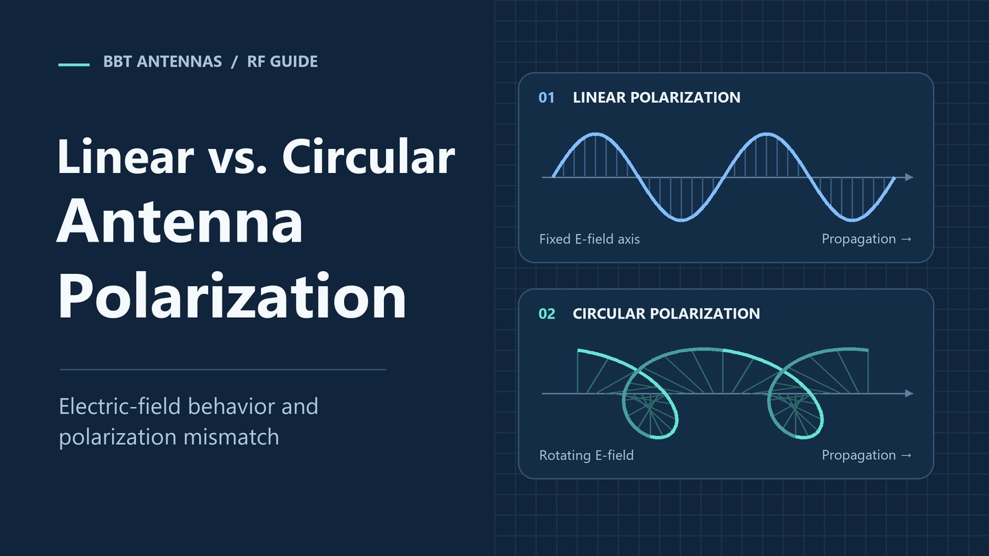
What Is Antenna Polarization?
Antenna polarization is the orientation of the electric field in the radio wave that an antenna transmits or receives. A vertically polarized antenna radiates a vertical electric field, and a circularly polarized antenna radiates a field that rotates. The shape and feed of an antenna decide its polarization, but the label always describes the electric field. For full signal strength, the antennas at both ends of a link need matching polarization.
There are three types of antenna polarization:
- Linear polarization: the electric field moves back and forth in one fixed plane. Vertical, horizontal and slant (±45°) polarization are all linear and differ only in the angle of that plane.
- Circular polarization: the electric field rotates as the wave travels, completing one turn per wavelength. Under the IEEE definition, viewed from the transmitter along the direction of travel, right-hand circular polarization (RHCP) turns clockwise and left-hand circular polarization (LHCP) turns counterclockwise.
- Elliptical polarization: the general case between the two, where the rotating field traces an ellipse. Every real circularly polarized antenna is slightly elliptical, and its axial ratio shows how close it comes to a perfect circle.
A dual-polarized antenna belongs to a separate category. It places two linearly polarized ports at right angles in one housing, either ±45° slant or vertical and horizontal, and each port carries its own signal. Sector, DAS and WISP projects use them for MIMO, and our dual-polarized antenna guide covers how to choose one.
Linear vs Circular Polarization: Key Differences
Linear polarization delivers the strongest signal when both antennas line up, and the signal drops as one of them rotates. Circular polarization accepts a fixed loss of about 3 dB against any linear antenna and in return holds a steady level at every rotation angle.
| Comparison | Linear polarization | Circular polarization |
|---|---|---|
| How the electric field moves | Back and forth in one fixed plane | Rotates one full turn per wavelength as the wave travels |
| Sensitivity to rotation | High; the signal falls as the angle between the two antennas grows | Low; rotating a linear antenna at the other end has little effect |
| Signal when both ends match | Full signal when both antennas share the same orientation | Full signal when both antennas share the same handedness |
| Loss against a linear antenna | 0 dB aligned, 3 dB at 45°, complete mismatch at 90° (theory) | About 3 dB at any rotation angle |
| Reflections | Reflected copies can reinforce or cancel the direct signal | One reflection reverses the handedness, so an antenna of the same handedness rejects much of a once-reflected signal |
| Purity figure on the datasheet | Cross-polarization discrimination (XPD) | Handedness (RHCP or LHCP) and axial ratio |
| Typical uses | Cellular sectors, WiFi and WISP links, LoRa and VHF/UHF networks, RFID with fixed tag orientation | UHF RFID with mixed tag orientation, GNSS and many satellite links |
Polarization Mismatch Loss
The loss between two antennas depends on how their polarizations relate. The table lists theoretical values for ideal antennas.
| Antenna at one end | Antenna at the other end | Polarization loss (ideal) |
|---|---|---|
| Vertical | Vertical | 0 dB |
| Vertical | Slant 45° | 3 dB |
| Vertical | Horizontal | Complete mismatch in theory |
| RHCP or LHCP | Any linear antenna (vertical, horizontal or slant) | 3 dB |
| RHCP | RHCP | 0 dB |
| RHCP | LHCP | Complete mismatch in theory |
Ideal values. On a real site, reflections and each antenna's own cross-polarized leakage let a little signal through even at a complete mismatch, but a link should never depend on it.
How a Circularly Polarized Antenna Works
A circularly polarized antenna radiates two linear components at right angles to each other, with equal amplitude and a 90° phase difference. As one component reaches its peak, the other passes through zero, so their sum keeps a constant strength and turns steadily, one full rotation per wavelength. The component that leads sets the handedness. Common designs include a square patch fed at two points 90° out of phase, a single-fed patch with trimmed corners, and a helix.
The same picture explains the 3 dB figure. A linear antenna picks up only the component that lines up with it, and that component carries half of the circular wave's power.
Circular vs Linear Polarization for UHF RFID
For UHF RFID, choose circular polarization (RHCP) when tag orientation varies and linear polarization when every tag is mounted the same way. Most passive UHF tags use a dipole inlay, which is linearly polarized, and that fact drives the choice.
A circularly polarized reader antenna reads that tag at any rotation in the plane facing the antenna, because its rotating field always has a component lined up with the dipole. The cost is a fixed loss of about 3 dB. At the same gain and reader power, a circular antenna therefore reaches a shorter maximum read distance than a linear antenna aligned with the tags.
A linear reader antenna aligned with the tags delivers the longest read distance and a more selective read zone. When a tag turns 90° away from the antenna's orientation, it can no longer power up and goes unread.
A tag turned edge-on, with its dipole axis pointing straight at the antenna, picks up little from either polarization. Antenna layout solves that case, for example a second antenna mounted at a different angle.
Match the polarization to the way tags arrive at the read point:
| Application | Recommended polarization | Why | Where to start |
|---|---|---|---|
| Warehouse portals and forklift loads | Circular (RHCP) | Carton labels face every direction on a mixed pallet | Warehouse RFID portal antennas |
| Parking and vehicle identification | Circular (RHCP) | Windshield tags sit at different angles on cars, vans and trucks | UHF RFID panel antennas |
| Race timing | Circular (RHCP) | Tags on shoes, bibs and bike frames tilt and turn as athletes move | Floor mat antennas |
| Smart cabinets and shelves | Circular (RHCP) near-field | Items are stacked and turned in any direction | Near-field RFID antennas |
| Personnel passages and access gates | Circular (RHCP) | Badges and cards are carried at any angle | BBT-RFID09C05-145 |
| Conveyors and production-line stations | Linear | Every tag passes at the same position and angle, so no 3 dB is lost | BBT-RFID09H10 |
| Electronic license plates and toll lanes | Linear, matched to the tag | Each tag is mounted the same way on every vehicle | BBT-RFID12H030 |
| Narrow read zones that need the most distance | Linear | The full gain reaches aligned tags with no polarization loss | BBT-09PA12H045 |
RHCP vs LHCP: When Handedness Matters
Handedness matters when both ends of a link are circular. An RHCP antenna and an LHCP antenna are completely mismatched in theory, which is why GNSS receivers use RHCP antennas to match the RHCP signals that navigation satellites transmit. When a circular reader antenna reads linear RFID tags, handedness makes no difference, since the tag picks up the same half of the power from either. BBT circular RFID antennas, including our panels, slim panels, PCB, near-field and mat antennas, are right-hand circularly polarized (RHCP).
BBT Circular and Linear RFID Antennas
BBT builds three UHF RFID panels as matched pairs: an RHCP version and a horizontally polarized version with the same housing, gain, beam and connector. Because nothing else changes, you can pilot both polarizations at the same mounting point, swap one for the other on the same cable, and roll out the version that reads best.
| Housing and size | Gain | Beamwidth H / E | Connector | RHCP model | Horizontal model |
|---|---|---|---|---|---|
| Square panel, 445 × 445 × 30 mm | 12 dBi | 40° / 38° | N-type female | BBT-09PA12C040 | BBT-09PA12H045 |
| Square panel, 385 × 385 × 30 mm | 10 dBi | 45° / 60° | N-type female | BBT-RFID09C10 | BBT-RFID09H10-385 |
| Slim panel, 920 × 160 × 30 mm | 12 dBi | 60° / 18° | SMA female | BBT-RFID09C12 | BBT-RFID09H12-920 |
Figures come from BBT product datasheets, November 2026. All six models cover 902–928 MHz with VSWR ≤1.3. Front-to-back ratio is ≥17 dB for both square pairs and ≥20 dB for the slim pair.
More Linear and Circular Options
- Slim horizontal panels: the BBT-RFID09H08 (8 dBi, 90° / 55°, 490 × 100 × 23 mm) and the BBT-RFID09H10 (10 dBi, 90° / 38°, 920 × 100 × 23 mm) cover wide, shallow read zones along shelves, filing cabinets and production lines.
- Vertical PCB antennas: the BBT-RFID09V02-100 (2.5 dBi, 100 × 65 × 3 mm) and the BBT-RFID09V05-170 (5 dBi, 170 × 60 × 10 mm) fit inside equipment, from production-line fixtures to scanning robots. Our PCB RFID antennas range also includes RHCP models.
- Near-field antennas: available in circular or linear polarization, with custom sizes for smart cabinets, checkout counters and shelves. See our near-field RFID antennas.
- Regional bands: several BBT RFID series are also available in EU 860–868 MHz versions.
Four models cover the main read points. Three RHCP antennas serve long-reach lanes, compact read points and floor-level timing lines, and one horizontally polarized panel serves 920–925 MHz vehicle lanes.
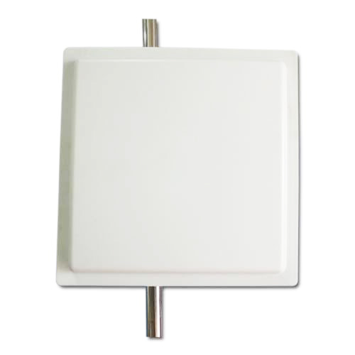
12 dBi RHCP Panel for Lanes and Doorways
BBT-09PA12C040
902–928 MHz · 12 dBi · RHCP
40° / 38° beam · VSWR ≤1.3
F/B ≥17 dB · 20 W · N-type female
445 × 445 × 30 mm · -40 to +60 °C
View Detail

5 dBi RHCP Wide-Beam Panel
BBT-RFID09C05-145
902–928 MHz · 5 dBi · RHCP
80° / 70° beam · VSWR ≤1.3
F/B ≥17 dB · 20 W · ABS radome
SMA male on LMR200 cable · 145 × 145 mm
View Detail

8 dBi RHCP Floor Mat for Race Timing
BBT-09RA08C060
902–928 MHz · 8 dBi · RHCP
60° / 60° beam · VSWR ≤1.3
F/B ≥20 dB · 20 W · TNC male
1090 × 520 × 30 mm · TPV + rubber
View Detail
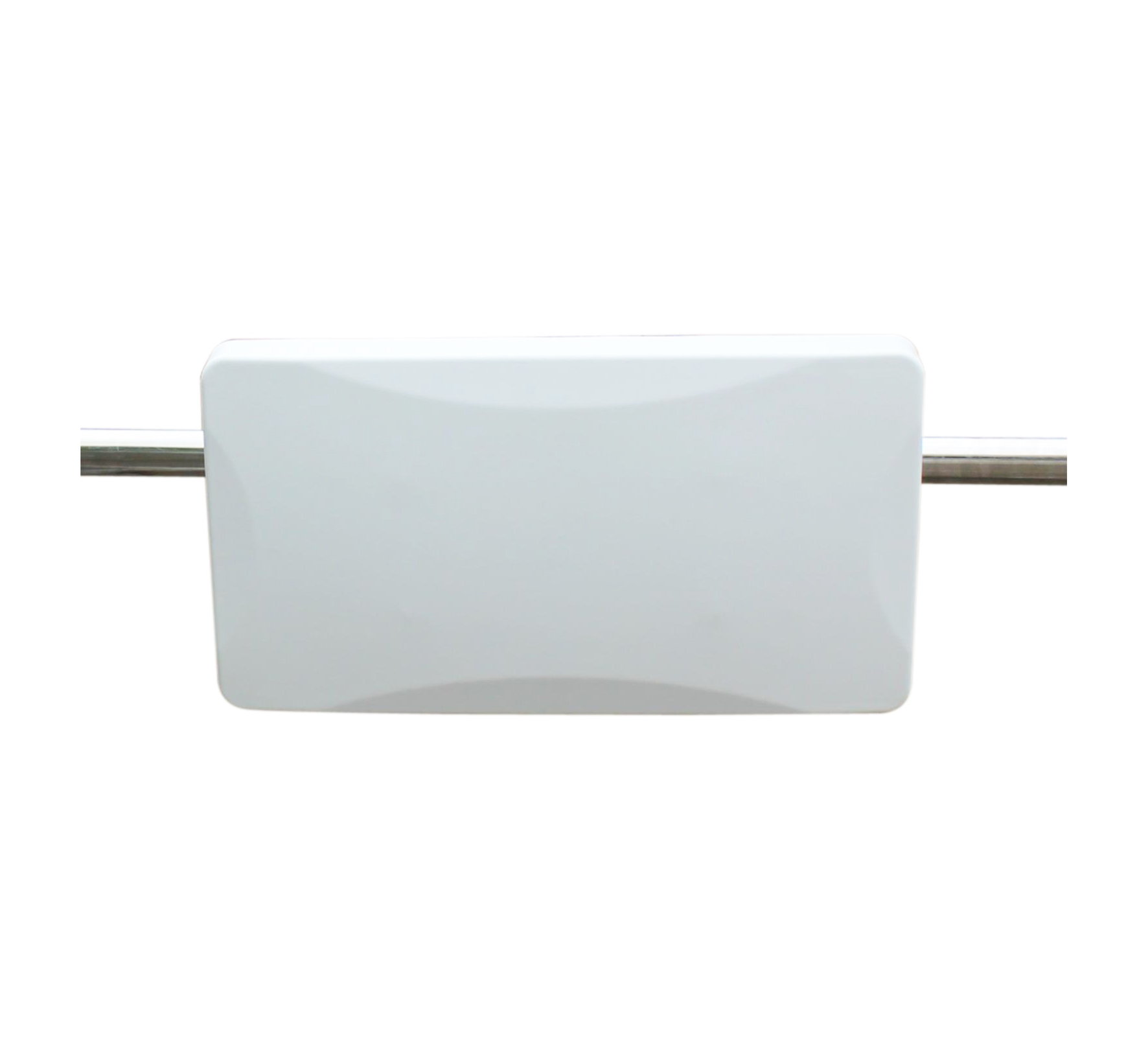
12 dBi Horizontal Panel, 920–925 MHz
BBT-RFID12H030
920–925 MHz · 12 dBi · horizontal
30° / 65° beam · VSWR ≤1.3
F/B ≥25 dB · 20 W · SMA female
500 × 270 × 60 mm · PC+ABS · 60 m/s
View Detail
Our engineers will recommend a circular or linear BBT antenna for your read zone and send you a quote as soon as possible.
Get an RFID Antenna QuoteWhich Polarization Do Other Wireless Systems Use?
Most cellular, WiFi and IoT networks run on linear polarization, while GNSS receivers and many satellite links use RHCP. Whatever the system, match the polarization at both ends of the link.
| System | Common polarization | Why | Where to start |
|---|---|---|---|
| 4G/5G base stations, DAS and sector panels | ±45° slant, two linear ports | Two ports give MIMO and polarization diversity from one antenna, and handsets are held at every angle | 4G/5G sector antennas |
| WiFi and WISP point-to-point and point-to-multipoint | Vertical and horizontal, two linear ports | Two orthogonal ports carry two MIMO streams over one link, and both ends must use the same pair of orientations | 2.4–6.4 GHz dish antennas Horn antennas MIMO sector antennas |
| LoRa, VHF/UHF private networks and IoT | Vertical | A vertical fiberglass omni covers 360° around the gateway and matches the vertical antennas on most end devices and radios | VHF/UHF and LoRa antennas |
| GNSS and many satellite links | RHCP | Matches the RHCP signals the satellites transmit and rejects much of the multipath that arrives after a single reflection | – |
| UHF RFID | RHCP or linear | Circular for mixed tag orientation, linear for tags mounted the same way | UHF RFID antennas |
Two installation points apply to every linear antenna:
- Mount it straight: a tilted antenna adds a mismatch angle to the link, and a 45° tilt costs 3 dB in theory. A vertical omni must stand plumb.
- Match the orientation at both ends: if one end is vertical and the other horizontal, the link loses most of its signal.
For sector, DAS and WISP antennas with two ports, see our guide to choosing a dual-polarized antenna for 5G, DAS and WISP projects.
Polarization Specs to Check on a Datasheet
Check the polarization type first, then the figure that shows how clean that polarization is: axial ratio for a circular antenna, cross-polarization discrimination for a linear one.
- Polarization type, stated in full: vertical, horizontal, ±45° slant, RHCP or LHCP. “Circular” without a handedness leaves a gap whenever the other end of the link is circular too.
- Handedness and axial ratio for circular antennas: axial ratio compares the longest and shortest axes of the polarization ellipse, in dB. The closer it is to 0 dB, the more circular the antenna, and the industry generally counts 3 dB or less as circular. Ask for the value across the whole band and over the main beam, and treat a single figure at the center frequency as incomplete.
- Cross-polarization discrimination (XPD) for linear and dual-polarized antennas: how strongly the antenna rejects the opposite orientation. Dual-polarized antennas should also list the isolation between their ports.
- Beamwidth in both planes: a circular antenna's read zone is not always symmetric. The BBT-RFID09C12, for example, pairs a 60° H-plane beam with an 18° E-plane beam for a fan-shaped read zone.
- Gain, VSWR and front-to-back ratio: compare these as on any antenna. Our guide to antenna gain vs directivity explains how gain relates to beam shape.
How to Choose Between Linear and Circular Polarization
The other end of the link sets the polarization you need, and how much its orientation varies decides between linear and circular. Five questions settle the choice for most projects.
- What is at the other end, and how is it polarized? A tag, a remote antenna or a satellite sets the starting point. Pair linear with linear in the same orientation, and pair circular with circular of the same handedness.
- Can you control its orientation? If every tag or remote antenna is mounted the same way, linear is an option. If orientation varies, choose circular.
- Do you need the longest distance or the steadiest reads? A linear antenna aligned with the other end reaches further. A circular antenna reads tags at any angle across the zone it covers.
- How much metal is on site? Racks, vehicles and machinery scatter signals and create dead spots. With mixed tag angles, circular polarization keeps reads more even. With fixed tags, aim a linear antenna along a clear path.
- Still unsure? Mount one of the matched pairs above at the real read point, compare read rates for both versions, and keep the one that performs best.
Why Buyers Source RFID and Wireless Antennas from BBT ANTENNAS
BBT ANTENNAS builds RFID antennas in both polarizations along with the dual-polarized antennas that cellular and WiFi networks rely on, so one supplier can equip the read points, links and coverage of a project.
- Both polarizations for RFID: RHCP and linear models across panels, slim panels and PCB antennas, RHCP mat antennas, near-field antennas in either polarization with custom sizes, and integrated RFID readers.
- Matched pairs for site trials: three RHCP and horizontal panel pairs share housing, gain, beam and connector, and several series come in EU 860–868 MHz versions.
- Cellular and WiFi coverage: sector, panel, dish and horn antennas with ±45° slant or vertical and horizontal dual polarization.
- Measured RF performance: gain and radiation patterns are measured in our microwave anechoic chamber. Read how our anechoic chamber testing works.
- Experience and quality systems: antenna work since 1991, more than 200 staff, ISO 9001:2015 and ISO 14001:2015 certification, a 30,000 m² R&D and production workshop, and four-stage quality control from raw materials to shipping.
We also offer OEM/ODM development when a project needs a custom band, size or private-label version.
Linear vs Circular Polarization FAQ
What is the difference between linear and circular polarization?
Linear polarization keeps the electric field of a radio wave in one fixed plane, such as vertical, horizontal or ±45° slant. Circular polarization rotates the field as the wave travels, either right-hand (RHCP) or left-hand (LHCP). A linear antenna gives the most signal when both ends line up and loses signal as they rotate apart. A circular antenna holds a steady signal at any rotation of the other end but loses about 3 dB against a linear antenna.
Is circular polarization better than linear for RFID?
It depends on how the tags are mounted. Circular polarization is the safer choice when tag orientation varies, as with cartons on pallets, windshield tags or race bibs, because it reads linearly polarized tags at any rotation. Linear polarization is the better choice when every tag is mounted the same way, because it avoids the 3 dB circular-to-linear loss and reads further at the same gain. BBT ANTENNAS supplies both.
Why does a circularly polarized antenna read a shorter distance than a linear one with the same gain?
Most passive UHF RFID tags are linearly polarized dipoles. A linear tag picks up only the part of a circular wave that lines up with it, which is half of the power, a loss of about 3 dB. A linear reader antenna aligned with the tag has no such loss, so at the same gain and reader power it reads further. The circular antenna gives up that 3 dB in exchange for reading tags at any angle.
What happens if the polarization of two antennas does not match?
The link loses signal. In theory, a vertical and a 45° slant antenna lose 3 dB, a vertical and a horizontal antenna are completely mismatched, a circular and any linear antenna lose 3 dB, and an RHCP and an LHCP antenna are completely mismatched. On a real site, reflections let a little signal through even at a full mismatch, but most of the link margin is gone. Match the polarization at both ends and mount linear antennas straight.
RHCP vs LHCP: does the handedness matter?
Yes, when both ends are circular. An RHCP antenna and an LHCP antenna are completely mismatched in theory, which is why GNSS receivers use RHCP antennas to match the satellites. When a circular reader antenna reads linearly polarized RFID tags, handedness does not affect the read, because the tag picks up the same half of the power from either. BBT circular RFID antennas are RHCP.
Is a dual-polarized antenna the same as a circularly polarized antenna?
No. A dual-polarized antenna has two separate ports, each linearly polarized and set at right angles to the other, usually ±45° slant or vertical and horizontal. Each port carries its own signal for MIMO or diversity. A circularly polarized antenna radiates a single rotating field. Cellular, DAS and WISP networks mostly use dual-polarized antennas, while UHF RFID readers facing mixed tag orientation and GNSS receivers use circular polarization.
Can BBT supply the same RFID antenna in circular and linear versions?
Yes. Three BBT UHF RFID panels come in matched pairs that share housing, gain, beam and connector: the BBT-09PA12C040 (RHCP) and BBT-09PA12H045 (horizontal) at 12 dBi in 445 × 445 × 30 mm, the BBT-RFID09C10 and BBT-RFID09H10-385 at 10 dBi in 385 × 385 × 30 mm, and the BBT-RFID09C12 and BBT-RFID09H12-920 at 12 dBi in 920 × 160 × 30 mm, all for 902–928 MHz. We also offer OEM/ODM when a project needs a custom version.
Not sure whether your tags call for circular or linear polarization? Our engineers will recommend the right BBT antenna for your read zone and quote as soon as possible.
Get Help Choosing Circular or Linear RFID AntennasPrefer to browse first? See our UHF RFID panel antennas.