

In this article, "standard DAS antennas" refers to conventional indoor coverage antennas that do not explicitly provide a low-PIM rating, or where the project specification does not list low-PIM as a mandatory requirement. This is not a unified industry certification category. Different manufacturers, carriers, and project owners define "standard" differently, and many 4G single-carrier or lower-power deployments perform well with these antennas.
What Makes a DAS Antenna "Low-PIM" and Why It Matters for Your Project
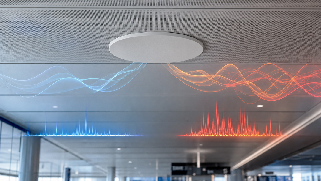
Passive intermodulation (PIM) is an unwanted signal generated when two or more RF carriers pass through non-linear junctions in a transmission path. In a distributed antenna system (DAS), these junctions include antenna feed points, connectors, solder joints, and even contact surfaces between dissimilar metals. The intermodulation products fall at frequencies determined by the carrier mix, and when they land in the receive band, they raise the noise floor of the system.
A higher noise floor directly reduces uplink sensitivity. In practical terms, this means shorter effective cell radius per antenna point, dropped connections at coverage edges, and lower data throughput, especially for users uploading files or running video calls. In multi-carrier environments where several operators share the same DAS infrastructure, PIM from one carrier's frequencies can degrade another carrier's receive channel.
A "low-PIM" antenna is not a separate antenna type. Ceiling-mount, wall-mount, directional panel, and log-periodic antennas can all be engineered for low PIM through material selection, mechanical design, plating processes, and controlled connector interfaces. The designation refers to the tested and guaranteed intermodulation performance under specified conditions, not the antenna form factor.
Whether your project needs that level of PIM control depends on the RF environment you are building. A 50 W multi-carrier feed driving dense antenna points in an airport terminal operates in a fundamentally different PIM risk category than a 5 W single-carrier system covering a small office floor.
When Does Your Project Actually Need Low-PIM Antennas?
Not every indoor coverage project carries the same PIM risk. The decision to specify low-PIM antennas should be driven by your actual project conditions, not by a blanket rule.
High-Risk Conditions That Call for Low-PIM Specs
- Multi-carrier DAS: Systems carrying 2G, 3G, 4G LTE, and 5G NR simultaneously across multiple frequency bands create more intermodulation combinations.
- High composite power: When the total RF power reaching each antenna port exceeds 20 W, or the aggregate feed power across all carriers is above 100 W, PIM products become stronger and harder to manage.
- High-density deployments: Venues like airports, stadiums, convention centers, and transit stations with closely spaced antenna points face higher mutual coupling and PIM accumulation risk.
- 5G NR capacity requirements: 5G systems using 256QAM modulation and UL MIMO are more sensitive to noise floor increases. Even moderate PIM that a 4G-only system would tolerate can measurably reduce 5G throughput.
- Carrier or building owner PIM compliance: Many mobile operators and large building owners now include PIM performance requirements in their DAS deployment contracts.
- Long-term SLA or maintenance contracts: PIM performance can degrade over time as connectors oxidize and mechanical joints shift. Projects with long service commitments benefit from starting with verified low-PIM components.
When Standard DAS Antennas Are a Practical Choice
- Single-carrier or narrowband coverage with low composite power (under 5 W per port)
- Warehouse, parking structure, or industrial coverage where uplink sensitivity is less critical
- Budget-constrained projects with no carrier PIM compliance requirement
- Temporary or short-term installations where long-term PIM degradation is not a concern
| Condition Favoring Low-PIM | Condition Where Standard May Suffice |
|---|---|
| Multi-carrier (3+ bands sharing one DAS) | Single-carrier or dual-band only |
| Per-port power above 20 W | Per-port power under 5 W |
| Dense antenna spacing in high-traffic venues | Sparse spacing in low-traffic areas |
| 5G NR with 256QAM / UL MIMO | 4G LTE basic coverage |
| Carrier contract specifies PIM performance | No carrier PIM specification |
| 10+ year SLA / maintenance commitment | Temporary or short-term deployment |
How to Compare PIM Ratings Without Getting Misled
When you receive datasheets or quotations from different antenna suppliers, comparing PIM values requires more than looking at two numbers.
PIM Value, Unit, and Test Power Must Match
PIM is typically expressed in dBc (decibels relative to the carrier). A rating of −150 dBc means the intermodulation product is 150 dB below the carrier power level. A lower number (more negative) indicates better performance: −153 dBc is better than −150 dBc.
However, the test power determines the stress level applied to the antenna during measurement. An antenna tested at 2×20 W (2×43 dBm) faces a different thermal and mechanical load than one tested at 2×10 W. The same antenna will generally show worse PIM at higher test power. If Supplier A quotes −153 dBc at 2×20 W and Supplier B quotes −155 dBc at 2×10 W, you cannot conclude that B is better without normalizing the test conditions.
For reference, the BBT ANTENNAS 4T4R MIMO ceiling and wall-mount antennas specify their PIM performance as IM3 (2×43 dBm carrier) ≤ −150 dBc, clearly stating both the test power and the guaranteed limit. A properly specified datasheet should always include the test power alongside the PIM value.
If a supplier provides only a dBc number without test conditions, request clarification before you compare. Adding "PIM test power and method" to your RFQ requirements eliminates this ambiguity upfront.
Test Method and What It Tells You
PIM can be measured in a factory environment or on-site after installation. Factory testing (per the IEC 62037 series of standards) uses calibrated equipment, controlled ambient conditions, and freshly assembled connections. This establishes the antenna's inherent PIM performance as a manufactured component.
On-site PIM testing reflects the installed system, including connector torque, cable routing, mounting hardware, and environmental conditions. An antenna with excellent factory PIM can show poor on-site PIM if the installer over-tightens or under-tightens a connector, allows a cable to bend beyond its minimum radius, or introduces metal particles into a junction.
Both data points are valuable. Factory PIM confirms component quality. On-site PIM confirms installation quality. When evaluating a manufacturer, ask for factory test data. When commissioning a DAS, conduct on-site PIM sweeps as part of your acceptance procedure.
Complete Spec Checklist for DAS Antenna Selection
PIM is one critical parameter, but selecting the right DAS antenna requires checking the full specification set against your project requirements.
| Parameter | Why It Matters for Your Selection |
|---|---|
| Frequency Range | Must cover all carrier bands in your DAS band plan. Missing a band means adding a separate antenna or splitter. |
| Number of Ports | 4×4 MIMO antennas support higher 5G throughput than 2×2. Port count also affects isolation and connector logistics. |
| Polarization | Horizontal, vertical, or ±45° dual-polarized. Must match your DAS head-end and cabling topology. |
| Gain (dBi) | Higher gain extends coverage per antenna point but narrows the beam. Balance gain against spacing and mounting height. |
| Beamwidth (H/E-plane) | Determines the coverage footprint shape. Wider beamwidth covers more area per antenna at the cost of signal concentration. |
| VSWR | Lower VSWR means better impedance matching and less reflected power back to the DAS source equipment. |
| PIM Rating & Test Conditions | The core of this guide. Always check the dBc value, test power, and test method together. |
| Port-to-Port Isolation | Critical for multi-port MIMO antennas. Poor isolation degrades MIMO performance and can cause cross-carrier interference. |
| Connector Type | 4.3-10 connectors are the current DAS standard for low-PIM installations. Verify compatibility with your jumper cables. |
| Mounting & Dimensions | Ceiling-mount for open areas, wall-mount for corridors and perimeter coverage. Check plenum-rated and fire-code requirements. |
| IP Rating / Operating Temp | Indoor-only vs. indoor/outdoor rated. Extreme temperature ranges affect material expansion and long-term PIM stability. |
| Max Input Power | Must exceed your planned per-port power with safety margin. Underpowered antennas risk thermal damage and PIM drift. |
BBT ANTENNAS Low-PIM DAS Antenna Solutions
BBT ANTENNAS manufactures a range of DAS indoor coverage antennas, including 4T4R MIMO models designed for multi-carrier 4G/5G projects requiring verified low-PIM performance. Below are two standard models with their current specifications. For the complete DAS 5G antenna product line, visit the product category page.
4T4R MIMO Ceiling and Wall-Mount Antennas
Frequency: 617–960 / 1710–2700 / 3300–4200 / 4900–6000 MHz (4 bands)
Gain: 3 / 4.5 / 5.5 / 6 dBi | Polarization: Horizontal ×4
VSWR: ≤1.8 | IM3 (2×43 dBm carrier): ≤−150 dBc
Port Isolation: ≥15 / ≥20 / ≥23 / ≥23 dB
Connector: 4×4.3-10 Female | Dimensions: Φ360×18 mm | Max Power: 50 W
Frequency: 698–960 / 1710–2700 / 3300–4200 / 4200–6000 MHz (4 bands)
Gain: 6 / 9 / 8 / 7 dBi | Polarization: ±90°
VSWR: ≤2.0 | IM3 (2×43 dBm carrier): ≤−150 dBc
Front-to-Back: ≥16 / ≥20 / ≥16 / ≥15 dB | Isolation: ≥20 / ≥25 / ≥25 / ≥30 dB
Connector: 4×4.3-10 Female | Dimensions: 390×280×70 mm | Max Power: 50 W
Both models use 4.3-10 female connectors, the current industry-preferred interface for low-PIM DAS installations. The four-band coverage from sub-1 GHz through 6 GHz supports simultaneous 4G LTE and 5G NR service across global carrier band plans.
OEM/ODM and Custom Design Options
The specifications above represent standard catalog models. If your project requires different frequency band combinations, a specific PIM target beyond the standard rating, a different port count, alternate connector types, or custom radome dimensions and colors, BBT ANTENNAS provides OEM/ODM and custom antenna design services.
BBT operates a 30,000 m² antenna manufacturing facility in Foshan, Guangdong, with over 200 employees covering RF design, simulation, prototyping, testing, and quality control. The facility holds ISO 9001:2015 and ISO 14001:2015 certifications and is equipped with third-order intermodulation test instruments, environmental chambers, and network analyzers. For brand owners, distributors, and system integrators sourcing private-label or project-specific DAS antennas, BBT handles the full cycle from RF design through volume production.
Frequently Asked Questions
What PIM rating should I specify for a multi-carrier 4G/5G DAS project?
There is no single universal PIM threshold for all projects. However, many carrier specifications and large-venue DAS contracts reference IM3 ≤ −150 dBc at 2×43 dBm (2×20 W per carrier) as a baseline for multi-carrier deployments. Your actual requirement depends on the number of carriers, composite power, antenna density, and the carrier's own network standards. Always confirm with your carrier or network planner before finalizing the PIM spec in your RFQ.
Can I compare PIM values from different datasheets directly?
Only if the test power and test method are identical. A PIM rating of −153 dBc tested at 2×20 W and −155 dBc tested at 2×10 W are not directly comparable because PIM products increase with applied power. When evaluating multiple suppliers, request that all PIM data be provided at the same test power level, or specify your required test conditions in the RFQ.
Does every indoor DAS project need low-PIM antennas?
No. Single-carrier systems with low per-port power (under 5 W), basic 4G coverage in warehouses or parking structures, and temporary installations can typically use standard DAS antennas without PIM-related performance issues. Use the project conditions table in this guide to determine whether your specific deployment warrants low-PIM specification.
What is the difference between factory PIM testing and on-site PIM testing?
Factory PIM testing measures the antenna as a manufactured component under controlled conditions with calibrated equipment and new connections. On-site PIM testing measures the installed antenna system, including the effects of connector torque, cable routing, mounting hardware, and the surrounding environment. Factory data validates component quality; on-site data validates installation quality. Both are important for a reliable DAS deployment.
Can BBT ANTENNAS customize PIM specs, frequency bands, or connectors for my project?
Yes. BBT ANTENNAS provides OEM/ODM and custom antenna design services from its 30,000 m² manufacturing facility. Customization options include frequency band combinations, PIM targets, port configurations, connector types, radome dimensions and colors, and private-label branding. Contact BBT with your project requirements for a custom design consultation and quotation.
How does antenna connector type affect PIM performance?
The 4.3-10 connector has become the preferred interface for low-PIM DAS installations because its hand-tightenable design provides consistent torque, reducing the installation variability that causes PIM in the field. Compared to traditional 7/16 DIN connectors, 4.3-10 connectors are more compact and lighter, making them practical for high-density ceiling and wall-mount deployments. Both BBT 4T4R MIMO DAS antenna models use 4.3-10 female connectors.
Ready to source low-PIM DAS antennas for your 4G/5G project?
Contact BBT ANTENNAS for standard model datasheets, custom design consultation, or a project quotation.
Request a Quote