
Selecting the right LoRa gateway antenna starts with matching your project's frequency band, then choosing the gain and radiation pattern for your coverage area, planning the cable run and connector, and confirming performance with a field test before you place a volume order.
Last updated: September 2026
LoRa gateway antennas: what they do and why the gateway side matters
In a LoRa or LoRaWAN network, every sensor node talks to a gateway. The gateway antenna is the single biggest hardware lever you have for extending coverage: it controls how far, how reliably, and in what pattern the gateway receives signals from the field.
Node-side antennas are constrained by device size, battery, and enclosure. The gateway side gives you room to optimize. You choose the antenna gain, the installation height, the cable type, and the line of sight to your coverage area. A well-matched gateway antenna can double your effective range compared to a stock rubber-duck antenna shipped with a development gateway.
LoRa (Long Range) is a sub-GHz wireless protocol built for low-power, long-distance data transmission in unlicensed ISM bands. It can reach 10 to 15 km in open rural terrain, or 2 to 5 km in built-up urban areas, depending on the antenna, mounting height, and obstructions. Compared to WiFi and ZigBee (short range, high power consumption) or cellular NB-IoT (carrier-dependent, recurring airtime fees), LoRa gives project teams a private, low-cost wireless backbone that runs on battery-powered sensors for years without replacement.
The applications are broad. Municipal authorities use LoRa for water-level monitoring, street lighting control, and waste-bin sensors. Agricultural operations track soil moisture, weather stations, and livestock across thousands of hectares. Industrial facilities monitor pump vibration, tank levels, and environmental conditions in plants and power stations. In all these cases, the gateway antenna determines whether the network covers every sensor or leaves dead zones.
This guide walks through the selection criteria, installation factors, and field-testing approach that matter before you commit to an antenna order for your gateway fleet.
Frequency bands and regional compliance
Every LoRa deployment starts with a frequency decision. The ISM band your project uses determines which antennas, gateways, and nodes are compatible, and a frequency mismatch means the hardware will not work.
Three main LoRa frequency regions
- 433 MHz: Common in parts of Asia and Africa. Signals at this frequency propagate farther per watt and bend better around obstacles, but antennas are physically larger.
- 868 MHz (EU863-870): The standard for Europe, the Middle East, and parts of Africa. Most European LoRaWAN gateways ship with 868 MHz radio modules.
- 915 MHz (US902-928): Used across the Americas, Australia, and parts of Asia-Pacific. The wider channel plan supports higher throughput when needed.
Some regions also use 470-510 MHz (China, parts of Southeast Asia) or other sub-GHz allocations. Check your country's ISM-band regulations before selecting hardware.
Why frequency choice drives antenna selection
A 433 MHz fiberglass omni antenna is physically longer and has different gain characteristics than an 868 MHz or 915 MHz model with the same dBi rating. You cannot use an 868 MHz antenna on a 915 MHz gateway (or the reverse) without significant performance loss. Confirm your operating frequency first, then choose an antenna rated for that exact band.
BBT ANTENNAS manufactures LoRa fiberglass omni antennas for the three main ISM bands: 470-510 MHz (model BBT-0405FG03V, 3 dBi), 860-868 MHz (model BBT-08FG06V, 6 dBi), and 902-928 MHz (model BBT-09FG08V, 8 dBi), plus custom frequency options on request.
Gain, radiation pattern, and coverage planning
Gain measures how much an antenna concentrates energy in its preferred direction, expressed in dBi. A higher gain number does not mean the antenna adds power to your radio signal. It means the antenna compresses the signal into a flatter, wider disk: more reach toward the horizon, less coverage above and below.
For LoRa gateway antennas, common gain values range from 2 dBi to 9 dBi:
- 2 to 3 dBi: Wide vertical beam. A good fit for gateways installed on short masts or rooftops where nodes sit nearby and at varying heights relative to the antenna.
- 5 to 6 dBi: Moderate beam concentration. A practical starting point for most municipal and industrial projects where the gateway sits 10 to 20 meters above node level and covers 1 to 3 km.
- 8 to 9 dBi: Narrow vertical beam, maximum horizontal reach. Best for gateways at moderate heights covering flat, open terrain at longer range (3 to 10+ km in rural or agricultural areas).
Compare vertical and horizontal antenna patterns
For typical vertically mounted omnidirectional antennas, higher gain is often achieved by concentrating radiation into a narrower vertical beam. The diagrams below compare directional patterns.
Lower gain: typically wider vertically
The main lobe spans a wider range of elevation angles above and below the horizontal plane.
Higher gain: typically narrower vertically
The main lobe is concentrated closer to the horizontal plane, with a narrower spread of elevation angles.
Both remain omnidirectional horizontally
Viewed from above, an ideal omnidirectional pattern is circular: radiation extends around the antenna through 360°. The two lobes in each side view are a cut through the three-dimensional pattern.
Matching gain to installation height
Picking the wrong gain for your installation height is one of the most common mistakes in LoRa gateway projects. A 9 dBi antenna on a 30-meter tower compresses the beam so tightly that it overshoots nodes close to the base, creating a dead zone directly below the gateway. If your project involves a tall mast serving nodes within 1 to 2 km at ground level, a 5 or 6 dBi antenna often delivers more reliable coverage than a 9 dBi model with a narrower beam.
The reverse also applies: a 3 dBi antenna on a low rooftop wastes energy above the horizon and limits your horizontal range. Match the gain to your mounting height and the distance to your farthest nodes.
Omnidirectional vs. directional
Most LoRa gateway antennas are omnidirectional, radiating signal evenly around the horizontal plane. This pattern suits projects where nodes are scattered in all directions around the gateway.
If your nodes are concentrated in one direction (a sensor line along a river, a pipeline, or a single farm field), a directional antenna such as a Yagi or panel antenna can double your effective range in that direction by focusing the beam. BBT ANTENNAS offers both omnidirectional fiberglass models and directional antennas in the VHF/UHF/LoRa/IoT range.
Installation, cable, and connector considerations
Where you mount the gateway antenna, what cable connects it to the radio, and which connector interface you use all affect the signal that actually reaches your sensor nodes.
Mounting position
- Rooftop or building top: The most common choice for urban and suburban gateways. Mount the antenna on a short mast or bracket above the roofline, clear of metal obstructions. Use a lightning arrestor and proper grounding on the cable run.
- Independent mast or tower: Required for wide-area coverage in open terrain, such as agricultural monitoring, water-level infrastructure, or environmental sensing. Heights of 10 to 30 meters are typical. The taller the mast, the greater the line-of-sight coverage, but choose the antenna gain to match (see the section above).
- Pole or street-light mount: A practical option for municipal IoT projects covering a few city blocks. Quick to install and easy to maintain.
- Indoor (fallback only): Walls and roofing materials absorb and reflect LoRa signals, reducing range by 50% or more compared to a clear outdoor path. Avoid indoor gateway antenna placement whenever possible. If indoor mounting is unavoidable, position the antenna near a window with a clear view toward the coverage area and expect reduced range.
Cable selection and signal loss
The coaxial cable connecting the antenna to the gateway radio introduces signal loss. At LoRa frequencies (400 to 928 MHz), this loss grows with cable length and operating frequency. Choosing the wrong cable can wipe out the advantage of a good antenna.
| Cable type | Loss at 868 MHz (per 10 m) | Best for |
|---|---|---|
| LMR400 | ~1.8 dB | Permanent outdoor runs, 10-30 m |
| LMR200 | ~3.8 dB | Shorter runs under 10 m where LMR400 is too bulky |
| RG316 | ~8 dB | Pigtails and jumpers under 1 m only |
Rule of thumb: keep the cable as short as possible. If the cable run exceeds 10 meters, use LMR400 or a comparable low-loss grade. Using 10+ meters of RG316 on a gateway is a common engineering mistake that costs you 8 dB or more of signal, cutting your effective range in half before the antenna even enters the picture.
BBT ANTENNAS supplies RF cables (LMR400, LMR240, LMR200, LMR100, RG316, RG178, RG142, and 1.13 cable) alongside its antenna products, so you can source matching cable and antenna from a single supplier.
Connectors
LoRa gateways and antennas commonly use three connector families:
- N-type: Large, weatherproof, threaded. The standard for outdoor fiberglass antennas and professional gateway installations. BBT LoRa fiberglass models typically ship with N Female or N Male connectors.
- SMA: Smaller, common on indoor gateways and development boards.
- U.FL / IPEX: Miniature snap-on connector used on PCB-mount antennas and embedded radio modules.
Confirm your gateway's connector type before ordering an antenna. Adapters are available but add insertion loss and a potential failure point at every junction.
Outdoor protection
For permanent outdoor installations, choose an antenna with a weatherproof housing rated for your site conditions. Fiberglass radome construction (the type used in BBT ANTENNAS outdoor LoRa models) resists UV exposure, rain, salt spray, and temperature cycling. Seal all outdoor cable connections with self-amalgamating tape or weatherproof boots to prevent moisture ingress.
Field testing before you buy in volume
Ordering the right antenna is easier when you base the decision on measured data from your own site. Before committing to a bulk purchase, run a field test with samples.
How to run a comparative antenna test
- Install the gateway at your planned location with the first antenna candidate.
- Deploy sensor nodes (or a test transmitter) at representative locations: the farthest point, the most obstructed path, and a mid-range reference point.
- Log RSSI (received signal strength indicator), SNR (signal-to-noise ratio), and packet delivery rate from each node for at least 24 hours. LoRa propagation changes with weather, temperature, and daily activity patterns, so short tests can be misleading.
- Swap the antenna for the second candidate and repeat the measurement. Keep the gateway location, cable, and node positions identical so the only variable is the antenna.
- Compare the results. The antenna that delivers stable connectivity to your edge nodes with acceptable packet loss is the right choice, regardless of which one has the higher rated gain on paper.
What to record during each test run
- Antenna model, gain rating, and mounting height
- Cable type and length
- RSSI and SNR at each test node location
- Packet delivery success rate (packets received vs. packets sent)
- Date, time window, and weather conditions
- Any visible obstructions, reflections, or interference sources noted during the test
BBT ANTENNAS provides product samples for evaluation before production orders. Contact the sales team with your frequency, mounting plan, and coverage target, and they will recommend antenna candidates to include in your field test.
BBT ANTENNAS LoRa gateway antenna options
The fiberglass omni antennas below cover two of the most common LoRa frequency bands deployed in Asia-Pacific and global IoT projects. Each model is designed for outdoor pole or mast mounting with an N-type connector, and all are available for OEM branding and custom cable or connector options.
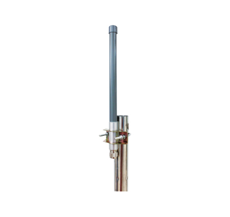
433MHz Fiberglass Omni Antenna
426-440MHz | 3 dBi | Vertical polarization
Long-range fiberglass omni for 433 MHz LoRa gateway deployments. N Female connector, outdoor-rated radome.
View Details
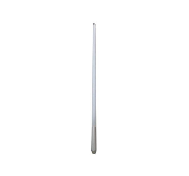
470-510MHz Fiberglass Omni Antenna
470-510MHz | 6.5 dBi | Vertical polarization
Higher-gain fiberglass omni for 470-510 MHz LoRa networks. Ideal for elevated gateway installations covering 2+ km in urban or suburban terrain.
View Details
Custom LoRa antenna design and OEM supply
If your project requires a specific frequency, gain, radiation pattern, connector, or housing that standard catalog models do not cover, BBT ANTENNAS can design and build it.
Three ways to work with BBT
- OEM (build to print): You provide a finished antenna design or reference sample. BBT manufactures it to your specification and applies your branding. Best for brands and distributors with a proven design that need reliable volume production.
- ODM (design and build): You provide a target specification or performance requirement. BBT's RF engineering team designs the antenna, then manufactures and private-labels it for your brand.
- Custom antenna design: You have a hard RF problem that off-the-shelf parts cannot solve. BBT designs, simulates, prototypes, and tests a new antenna around your requirements.
Manufacturing and quality
BBT ANTENNAS has been manufacturing communication antennas for over 30 years. The company operates a 30,000-square-meter R&D and production facility in Foshan, China, with 200+ staff including a seven-role RF and microwave engineering team covering design, simulation, structural engineering, quality control, trial production, and commissioning.
Products and processes hold 60+ certifications, including ISO 9001:2015 and ISO 14001:2015. Every antenna goes through a four-stage QC system (raw materials, production process, final assembly, shipping) and is measured in the company's in-house anechoic chamber and environmental testing lab (thermal shock, UV aging, rain, salt spray, drop testing).
For LoRa gateway projects, you can customize the frequency band, gain level, connector type, cable length, housing material, mounting hardware, color, silkscreen, and packaging. Start with samples, confirm performance in the field, then move to volume production with your branding applied.
Frequently asked questions
Can one LoRa gateway operate on both 433 MHz and 868 MHz at the same time?
Does higher antenna gain always mean better coverage?
How much signal does a long cable run cost?
Should I install the gateway antenna indoors or outdoors?
Can BBT ANTENNAS build a LoRa antenna to my frequency and gain specification?
How should I arrange a LoRa antenna sample test before placing a bulk order?
Get help selecting your LoRa gateway antenna
Share your project frequency, coverage area, and mounting plan. BBT ANTENNAS will recommend antenna options and send samples for your field evaluation.
Request LoRa Antenna Samples